Additional Chip size; The BGA32!
NoxyNixie opened this issue · 2 comments

While messing about with the Circuit Designer I reasonably quickly found that I actually wanted a few more IO pins. Trying out some things I found you could actually cram 17 pins on a single circuit design. Rounding that down to a power of two brings that to a neat 16 pins.
I'm not entirely sure about what the actual block would look like but initially I was thinking about a full black top (the BGA chip) with two layers of socket in and out on all sides of the block giving a total of 32 sockets IO followed by one layer of power in socket. Pretty much making it a full block (or nearly a full block if you want to inset the BGA a little bit). You could actually put the power sockets on the bottom making the chip a layer lower.
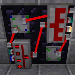
Trying out all the pins in the debugger seems to work like a charm so I suspect technically it should be quite possible:

The above isn't really a good example or a reason for a 32 socket chip however I can already envision the fun I'd have with a BGA32 ;)
You could actually do a BGA16 as well with all the sockets at the bottom like a real BGA chip and the power sockets on the sides.
Either way love the mod and I think the addition of these BGA variants would make for more fun!


If your I/O mainly uses On/Off logic signals you can expand using Binary Signal Splitters/Combiners giving you a total of 256 (DIP8) or 384 (QFP12) "effective pins".
But when using numeric signals, I see that more actual pins would indeed be useful.
My current implementation actually has a limit of 31 outputs (no limit on inputs) but I'm currently not sure if I enforced that limit or if things just break then. At least the limited space in the editor prevents you from ever reaching that number ;)
The BGA16 (back side filled with pins) sounds most reasonable to me, it would then also have the same pin setup as the Signal IO Controller (OpenComputers bridge).
Another Idea that I recently got is some kind of "Integrated Control Panel":
Modules placed on the panel won't be directly connected to ports on the back but instead go through a custom internal circuit first. But I'm not fully sure yet how assembly and internal wiring would be done.
Maybe have IOs in the editor named like [13] be connected to the Input/Output of the module placed on first cell from the left of third row from bottom, etc.